
Description
Features:
- Hand Held Instrument
- Easily locates shorted bolts, replaces bolt to bolt
- Use on structure with or without CP
- Uses Radio Frequency to test effectiveness of above ground insulators
- Auto Shut-Off feature
Includes:
- Probe, Red with lead wire and needle point tip
- Probe, Black with needle point tip
- Additional needle tips, stored in small black vinyl tubes
- (6) AA Batteries
- Instructions Manual
- Warranty Card
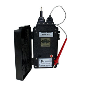
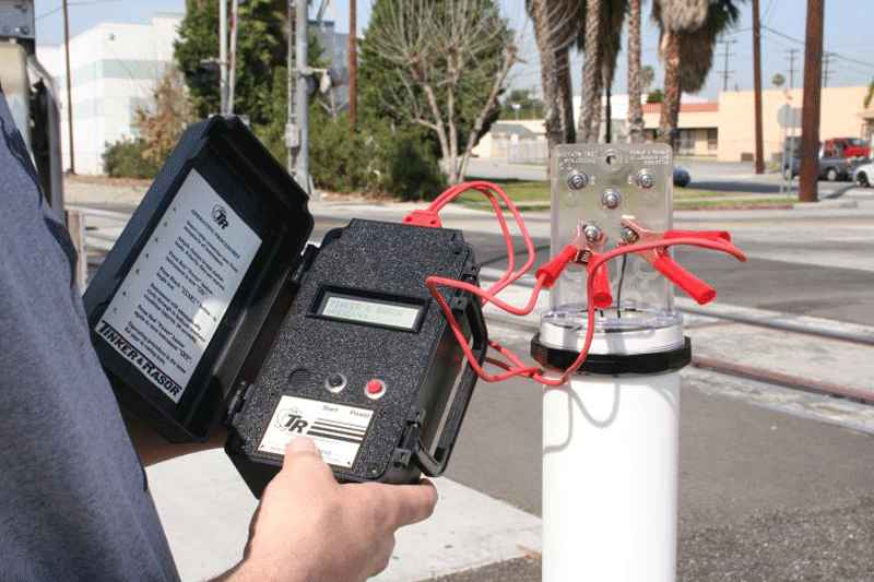
The Model RF-IT is a highly sensitive device used to test above ground pipeline insulators. This affordable unit is also fantastic for flange bolts shorts. The automatic RF-IT allows the operator to pinpoint the precise contact point. The RF-IT emits an audible beep. When the operator gets closer to the point of contact the unit starts beeping faster. At the same time, the sliding scale LCD meter moves from right to left.
Download a Brochure
Radio Frequency instrument allows testing on structures under protection. Audible beep gets faster the closer to the point of contact. Use needle tipped probes to move bolt to bolt to find contact.
Download instructions
Download RF-IT Bulletin
Instructions for RF-IT Insulator Tester
IMPORTANT NOTE:
Do not use this instrument in an explosive environment.
Inspection of the instrument should be performed upon receipt. If damage has occurred in shipment, file a claim with the carrier immediately. If it is necessary to contact your supplier or Tinker & Rasor, be sure to include all information such as serial number, purchase order number and invoice number.
DESCRIPTION
The Model RF-IT is a highly sensitive device used to test above ground pipeline insulators. The automatic RF-IT allows the operator to pinpoint the precise contact point. The RF-IT emits an audible beep, and when the operator gets closer to the point of contact the unit starts beeping faster. A sliding scale LCD meter moves from left to right.
NOTE:
Newer Model RF-IT’s are using a digital meter that mimics an analog needle-type meter. Older RF-IT’s use a digital bar graph meter. Both meters sweep from right to left.
THEORY OF OPERATION
The RF-IT works using Radio Frequency. The Radio Frequency signal is applied to one side of a pipe by one of the two probes. The second probe then receives the high frequency signal. If the received signal is almost as strong as applied, the pipe is shorted.
The RF-IT has an internal band-pass filter which will filter out all the frequencies above and below 221kHz. This allows taking measurements on pipelines that are under cathodic protection or have other induced or impressed currents or signals.
It is important to note that because the RF-IT uses Radio Frequency to measure the effectiveness of an insulator, the measurement results can not be displayed in Ohms.
EQUIPMENT
The Model RF-IT Insulator Tester consists of a portable battery powered electronic instrument with detachable probes for making positive electrical contact across the insulator. The instrument is packaged in a plastic case complete with batteries ready to operate. Two extra steel needlepoint’s are supplied with the Tester.
The Model RF-IT Insulator Tester is factory calibrated and needs no field adjustments. Calibrations are made with the probe wire conductors supplied with the Model RF-IT Tester. Do not make changes or substitutes for probes & wires. If the instrument is turned on without both cables correctly inserted, the instrument will emit a loud continuous beep alarm.
Push the “RED” button on the panel to turn the Tester“ON”. Push again for the“OFF” position.
Note: If tester is not turned off manually, it will turn off automatically after 10 minutes. If Tester seems to fail during testing, the first thing to check is the“ON-OFF” switch. The built in timer is designed to save batteries in case the operator fails to turn the Tester “OFF” after each usage.
When the battery output becomes too low to power the instrument, the black lines on the LCD meter will flash on and off. Replace with (6) “AA” size alkaline batteries. Always put fresh batteries into the instrument. The Tester will operate properly until output battery voltage drops to 7volts DC.
Note: Older RF-IT’s with the bar graph meter do not show battery condition. The display will grow faint and begin to fade away as the battery output falls below 7v.
PRE-OPERATION CHECK OF THE MODEL RF-IT TESTER
Remove Black probe from lid of Tester and “INSERT” into either port locator on the front end of Tester.
Remove red probe from lid of tester and “INSERT” into the other port on the front end of Tester.Turn Tester “ON”
Observe LCD meter.
Meter should show black lines across the entire meter face.
Note: Older RF-IT Models show solid black square dots completely across the top and the bottom of the meter face. Between the bars, at each side, two black arrows should flash slowly.
The tester is equipped with audible signal and tone frequency varies from slow to fast according to resistance across probes. The lower the electrical resistance of the insulator the faster the frequency of the audible signal. The instrument will show 100% (black lines across the entire meter face) when the insulator is effective. When the meter does not show 100%, the insulator is not effective.
Tester is now ready to operate.
OPERATION TO CHECK SINGLE IN-LINE INSULATOR
Place the flexible cable (or solid) “red” probe’s steel needle to the opposite side of the insulator, making positive electrical contact to the metal pipe.
If insulator is “shorted”, (low electrical resistance) the LCD meter will be down low (left side of meter) towards the “0”. (Older meter, only one or two black square dot on both top and bottom rows on the LCD meter)
If the LCD meter reads 100%, all the way to the right side of the meter, the insulator is performing extremely well. (Older meter, the black square dots completely across the top and bottom rows)
LCD meter readings between these two extremes gives the operator the degree of quality of the insulator. The lower the LCD meter readings, the lower the electrical resistance of the insulator. Low resistance reading may be cause to watch for impending failure.
OPERATION FOR CHECKING INSULATED FLANGE BOLT(S)
On single insulated pipeline flange type insulators (where the bolts are insulated only halfway through the flange), make positive contact with the fixed probe of the Tester to the insulated flange and make positive contact with the flexible probe to each bolt on the same side of the flange. Read meter for every bolt. Meter readings will be same as when checking single in-line insulators described above.
On double insulated pipeline flange type insulators, make positive contact with fixed probe of the Tester to one side of a double flange and the flexible probe to each bolt, individually, on the opposite flange side. Read meter for every bolt. Meter readings will be the same as when checking single in-line insulators described above.
In the event an insulated flange indicates a definite electrical short, but all bolts indicate they are insulated properly, the electrical short exists across the flange insulator
BATTERY REPLACEMENT
Please see the photos below:
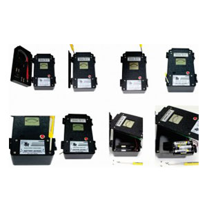
- Remove the four outer screws with a small Phillips-head screwdriver.
- Pry open the face with a small Flat-head screwdriver.
- Be careful of the wires attached to the readout.
- Remove battery holder.
- Replace (6) AA Batteries (T&R) replacement #010-002.
- Repeat steps in reverse once batteries are replaced.
All instruments being returned for repair should be sent PREPAID to either address below:
Ship Via Courier (UPS, FedEx, DHL, etc)
anjamgroup
Office No: 501, Makkah Tower
Custodian of the Two Holy Mosques Road,
Makkah Street Crossing,
PO Box 4160
Include with shipment information the nature of the problem, purchase order, serial number and return delivery address, phone and fax numbers. Immediate service is guaranteed!
THEORY OF OPERATIONS RF-IT:
 Download RF-IT Theory of Operations (pdf)
Use:
Test above ground pipeline insulators to pinpoint the precise contact point. The RF-IT emits an audible beep. When the operator gets closer to the point of contact the unit starts beeping faster. At the same time, the LCD meter moves from left to right.
Specifications:
- Battery Operated
- (6) Alkaline “AA” batteries (replaceable)
- Cables and probes included
Dimensions:
- 8″ x 4″ x 3″, 2 lbs. (203mm x 101.6mm xc 76.2mm, 0.907kg)
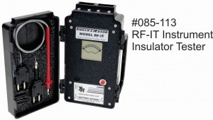
- #085-113 RF-IT Instrument – US$525.00
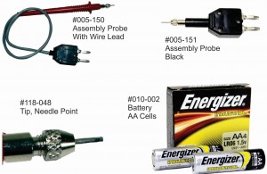
- #005-150 Assembly Probe Red w/Wire Lead – US$35.00
- #005-151 Assembly Probe Black – US$25.00
- #118-048 Tip Needle Point – US$0.95
- #010-002 Battery, “AA” Cell – US$1.77 Each RF-IT Takes Six AA’s Each


Reviews
There are no reviews yet.