
Description
Features:
- Audio frequency 750cps
- Maximum 100v output
- Fine Tune knob and LED’s to easily match maximum impedance
- Interrupter feature on oscillator
- LCD meter on receiver
- Receiver loud speaker or headset use
- Holiday detection on buried pipe (PD/H)
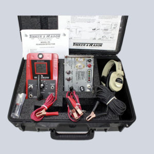
PD (Short Locator) Includes:
- Mark IV Receiver with battery
- PD Oscillator
- Headphones
- Battery Cables (set) (Red / Black)
- 30′ Ground Cable (Black)
- 6″ Red Oscillator to Pipe Cable (Red)
- (1) 9v Battery (Mark IV Receiver)
- Carrying Case
- Instructions Manual
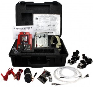
PD/H “Holiday Detector” Comes with everything above plus:
- Shoe Cleats (set of 4)
- Terminal Board (Single)
- Terminal Board (Double)
- 30′ Connecting Cable (White)
- Cleat Cables (Set of 4 -White)
For locating electrical shorts and open couplings on underground pipelines.
Download a Brochure
 Model M/1 Low Voltage Portable
Tinker & Rasor’s Model PD and the Null Method have been recognized as being the fastest method to accurately locate points of electrical contact and insulating joints on coated underground piping systems. The Tinker & Rasor Model PD is unaffected by parallel lines, depths, 60 Hz or ground cover, the survey can often be, in part, conducted from a moving vehicle over the pipe. In brief, the Null Method follows the flow of impressed audio frequency current in a coated pipe; determines where it leaves. This method is quite practical, particularly as competent field personnel can interpret findings quickly and accurately. The Model PD is also an excellent device for pinpointing defects in coatings on buried pipelines. This unit is also highly accurate in locating breaks in cables such as anode leads on impressed current, cathodic protection systems.
Recent Changes to the PD
You should be aware that we have made a few changes to the Model PD recently (08/30/04).
- The Oscillator (PD-C) has been updated to include LED lights instead of the meter, and the Output Indicator light has been replaced with a Fine Adjust knob. (See Model PD Product Instructions for more)
- The crystal in the Oscillator (PD-C) has been changed. There is a noticeable difference in the interrupt cycle rate from previous versions. The cycle is much faster now. This is an engineering change and not a problem with the instrument.
- The Model PD Complete Holiday Detector kit comes with connector cables to use between operators when conducting a Pearson Method Holiday Detector survey. The length of cable between operators has been shortened from 30′ to 20′.
Download instructions
1. Functions:
Pearson Type HolidayDetector:
The Tinker & Rasor Pearson type detector was designed to locate discontinuities, flaws or breaks in the coating of buried pipelines. This method makes possible the exact location of coating breaks in buried lines without access to the surface of the coated pipe. Locating electrical discontinuities aids in evaluating the application of a coating and also these discontinuities can be repaired to eliminate corrosion and to reduce the amount of current required for cathodic protection.
Short Location:
The apparatus is also effective in locating shorts or undesirable electrical contacts to a buried coated pipe. Such electrical contact should be removed prior to placing a pipeline under cathodic protection as these contacts would drain a large amount of protective potential from the coated pipe.
Pipe Locator:
The apparatus can be used very effectively as a pipe locator on coated pipelines which are electrically connected by a screw or welded joints. This application is particularly effective where it is desired to locate and follow one pipeline along a right-or-way where there are number of buried lines.
2. Operating Method:
Pearson Survey Method:
The method used to locate discontinuities is that of applying audio frequency A.C. energy between the coated pipe and ground. A traverse along the pipeline is made in with the difference in potential is indicated across approximately twenty to thirty feet of soil above the line. This potential difference is noted in the Receiver. When an area is reached where the difference in potential is considerably greater than the average potential over the pipe, a discontinuity is assumed to lie under this area.
Method of LocatingShorts:
The method of locating shorts or contacts on a coated pipe is that of applying a relatively large amount (five to fifteen watts) of audio frequency A.C. between the pipe and a remote ground connection. A traverse is made along the pipeline with a Receiver equipped with a search coil. A short or contact is observed along the traverse where the average A.C. signal picked up over the line suddenly drops to a very low level. This is assumed to be a point directly above the contact.
Method of LocatingPipe:
An audio frequency A.C. signal is placed between the coated pipe and a good ground connection.The Receiver, containing a search coil, is passed over the area where the pipe is assumed to be located. As the Receiver is moved back and forth in a horizontal plane over the pipe, a sharp null will occur in the received signal. The pipe to be located is assumed to be directly under this null. A well coated pipeline can be followed for a very great distance by this method when audio power of from five to fifteen watts is applied to the coated pipe.
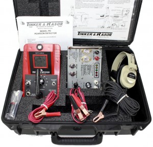
3. Apparatus:
The complete apparatus furnished with the Pearson-type detector comprises the following:
- Solid state Oscillator
- Solid state Receiver with filter
- Lightweight headphones w/ plug and cushions
- Shoe cleats
- Connecting cables
- Carrying Case
The Oscillator provided with the set has been designed to use the latest developments in this type of instrumentation. A signal of 750 C.P.S. is generated by using a power transistor switching circuit. This arrangement eliminates troublesome vibrators, buzzers or other moving part elements.The Oscillator converts low voltage (12 volts) D.C. to stable audio frequency A.C. directly; hence, by a highly efficient method, the input current to the Oscillator is only 1.7 amperes for a full output of 15 watts, a conversion efficiency of better than 80%. A maximum of energy can be transferred from the Oscillator to the pipe, the output of the Oscillator is provided with taps so that voltages of 2.5, 5, 7.5, 15, 50 and 100 volts are available to match the load.
An interrupter is provided to make the signal more easily recognized. The interrupter is actuated by a switch on the panel of the Oscillator. The Oscillator will produce 15 watts of 750 cycle signal into a 500 ohm load with the output selector set at the 100 volt position.
NOTE: Model PD-C (Rev. B) uses a new crystal that produces an interrupt frequency at a faster rate than previous models. Users familiar with this instrument may notice the difference.
The Receiver employs a high gain amplifier and a sharply tuned 750 cycle filter. Modern circuit design insures maximum circuit stability even when operated at ambient temperature extremes. The filter attenuates A.C. power line and other interference, permitting operation in the vicinity of high tension lines.
A loudspeaker is built into the Receiver, eliminating the need for earphones except in noisy areas. Plugging the earphones into the jack marked PHONES disables the loudspeaker. A search coil is contained within the receiver and is normally connected to the Receiver input.
Plugging the cable from the cleat terminal board into the jack marked CLEATS automatically disconnects the search coil and connects the cleats to the amplifier. The meter gives a visual indications of signal intensity and also serves to check battery conditions.
To test the battery, turn the Receiver on and push the button marked BATTERY TEST. Replace battery if necessary.
The Shoe Cleats provided with the detector have been designed for maximum foot comfort and for the most effective ground contact. All necessary connecting cables are furnished. Terminal boards with belt loops are furnished to provide a convenient means of making the necessary connections between shoe cleats and the Receiver.
4. Unpacking and Inspection:
Note the placement of the various components as received and repack into the same manner when not in use. If damage has occurred in shipment, file a claim with the carrier immediately. If it is necessary to contact your supplier or manufacturer concerning damaged or missing items, be sure to include all the information such as serial number, purchase order number and invoice number. This will assure you of obtaining proper and expeditious service.
5. Operating Instructions:
Pearson Survey: (Also see condensed Operating Instructions)
The following components are required for a Pearson Survey of a buried pipeline
- Oscillator with connecting cables
- Twelve volt storage battery (not furnished)
- Receiver
- Two sets of shoe cleats
- Cleat connecting cables
- Terminal Boards
The audio Oscillator is placed along the pipeline at a point where an electrical connection can be made to the pipe. Test point lead wires are convenient connections.The pipe lead wire is connected to the terminal of the Oscillator marked PIPE. Connect a wire from the terminal marked GROUND to some metal structure which is in good electrical contact with the earth. If no structure is available, a rod can be driven into the earth at a point from 20 to 30 feet from the pipe at right angles to the pipeline.
Connect a 12-volt storage battery to the battery terminals, observing correct polarity (red is positive or+, black is negative or -). Set the output voltage switch to 2.5, the interrupter switch to “OFF”, and the battery switch to “ON”. The Fine Adjust knob should be advanced all the way to the Right (MAX). Next, advance the output voltage control until the LED lights on the Oscillator show Red. Then move the Fine Adjust knob to the Left (MIN) until the LED lights show Green.
NOTE: Model PD-C (Rev. B) uses a new crystal that produces an interrupt frequency at a faster rate than previous models. Users familiar with this instrument may notice the difference.
If overloaded, circuit breaker will trip. To reactivate, reduce driving voltage and reset circuit breaker.
Turn the interrupter switch “ON”, if desired, and the Oscillator is ready for use.
For the most recent Oscillator, PD-C (Rev. B), the instructions are:
1. Connect 12 volt battery, observing polarity.
2. Connect to pipe and ground. Output Voltage to 2.5, Fine Adjust all the way to the Right (MAX).
3. Interrupter to OFF. Battery to ON.
4. Advance Output Voltage until Red LEDs light. Move Fine Adjust towards MIN until Green LED lights.
5. Interrupter to ON. Instrument is now ready for use.
NOTE: Model PD-C (Rev. B) uses a new crystal that produces an interrupt frequency at a faster rate than previous models. Users familiar with this instrument may notice the difference.
The terminal boards should be attached to the belts of the operators. (The board with the cord and plug is used by the operator who carries the Receiver).
Both operators fasten cleats on their shoes, then attach cleat cable to each cleat, running the cables up their legs. The key operator connects with wires from both of his cleats to the lower terminal on his terminal board. The secondary operator connects the wires from both of his cleats to the lower terminal on his terminal board. The secondary operator connects the wires from both of his cleats and on the end of the long connecting cable to his terminal board. The other end of the connecting cable goes to the upper terminal of the key man’s terminal board. The plug coming from the key man’s terminal board is plugged into the jack marked CLEATS, the Receiver is turned “ON”,and the apparatus is ready for use.
The traverse along the pipeline is made by walking over the pipe at a slow pace. Beginning adjacent to the Oscillator, set the Receiver volume so that the signal from the Oscillator can be heard at a very low level. As progress away from the Oscillator is made, the signal may drop and the level can be raised again by increasing the volume. A discontinuity is indicated by an increase in average signal level, followed by a relatively sharp decrease, then another increase and then back to normal level as progress is made over the discontinuity.
The exact point of discontinuity lies under the point of decreased signal or null.. This, then, is the point halfway between the two operators. If a series of discontinuities exist in close proximity to each other, the null effect may not be heard,or very difficult to observe. In this case, one man walks along the line and the other walks at right angles to the line and a discontinuity is noted by an increase in signal directly over the fault.
Locating Shorts or Contacts:
The following components are required for locating line shorts:
- Oscillator and 12 volt auto battery
- Oscillator to pipe cable
- Remote ground connection
- Receiver
The Oscillator and ground connections are made in the same fashion as described in the Pearson Survey above. Turn on the Oscillator and Receiver. Advance the Receiver sensitivity control until the 750 cycle tone is heard in the loudspeaker and the signal intensity meter reads slightly less than full scale. As the Receiver is moved back and forth across the pipe to which the Oscillator is connected, a very sharp decrease, or null, in the received signal will be observed when the Receiver is directly over the pipe.
Using this null method, it is possible to trace the path of the pipeline as long as there is a relatively large amount of audio current flowing in it. If the coated pipe is in contact with a foreign system, the audio current will leave the coated pipe at this point and audio current will flow in the foreign system. The same null effect will then be present on the foreign system as on the coated pipe from audio Oscillator to point of contact.
Locating Pipelines:
The apparatus and method required for locating welded or screwed pipe is the same as fo rlocating shorts or contacts. After connecting the Oscillator, hold the Receiver level over the ground and note the intensity of the received signal. As the Receiver is brought near the pipe, the signal will gradually increase and then will null sharply as the Receiver passes directly over the pipe. It is also possible to determine the depth of a pipe. First mark its exact center, using the method described above.
Once the center line of the pipe has been accomplished, it is relatively easy to measure the depth by triangulation. In order to determine the depths of pipes, it is necessary to position the Receiver in a 45 degree angle to the ground surface. This is accomplished by holding the Receiver so that its longest axis is perpendicular to the path of the pipe and then tilting it back until the air bubble in the depth angle gauge lies between the outer edge of the center ring and the black border.
Starting at the point directly above the pipe center line, and keeping the Receiver as close to the surface as possible without scratching it on the ground, move slowly away from the pipe at a right angle, maintaining the Receiver at 45 degree.When a new null or minimum signal is obtained, the depth of the pipe below the surface is the same as the distance between the center line of the pipe and the leading edge of the Receiver.
6. Battery Replacement:
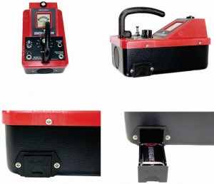
- Make Sure PD instrument is off.
- Battery door is located on the right-hand side of the instrument.
- Lift and push the battery door until it opens.
- Replace the single 9 volt Battery. T&R #010-007
- Push battery door until it latches closed.
- Resume operation of the instrument.
7. Shipping Instructions:
All instruments being returned for repair should be sent PREPAID to either address below:
Ship Via Courier (UPS, FedEx, DHL, etc)
Tinker & Rasor
ATTN: Repairs
791 S. Waterman Ave.
San Bernardino, CA 92408
Ship Via US Postal Mail
Tinker & Rasor
ATTN: Repairs
PO BOX 1667
San Bernardino, CA 92402-1667
Include with shipment information the nature of the problem, purchase order, serial number
and return delivery address, phone and fax numbers. Immediate service is guaranteed!
Tech Data:
Recommendations: Industries
- Gas
- Petroleum
- Chemicals
- Water
Dimensions:
- PD case 16″x8″x20″
- PD/Short case shipping weight, 15 lbs.
- PD/H Complete shipping weight, 19 lbs.
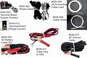
PD/S Parts List
Parts & Accessories Available
- #085-089 Mk IV Instrument – US$504.00
- #085-129 PDC Ocillator Instrument – US$504.00
- #010-007 Battery, 9 Volt – US$3.45
- #026-009 Cable, Battery, PD(Blk-Red) – US$15.18
- #026-010 Cable, Ground 30′, PD(Blk) – US$22.77
- #029-040 Carrying Case – US$221.38
- #082-007 Insert, Form, Case, PD Short – US$135.98
- #115-002 Headphones, Mono – US$31.63
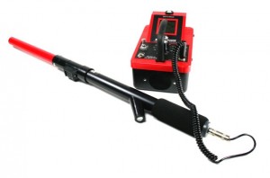
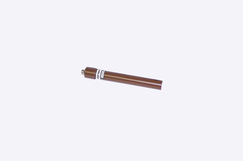
- The 45/90 Probe with telescopic handle – US$205.00

PD- Oscillator with the 45/90 Probe
PD/S Parts List
Parts & Accessories Available
- #085-089 Mk IV Instrument – US$504.00
- #085-129 PDC Oscillator Instrument – US$504.00
- #026-006 Cable Cleats set of 4 – US$33.00
- #026-008 Cable Connecting Lead 20′ – US$12.65
- #026-009 Cable, Battery PD(Blk-Red) – US$15.18
- #026-010 Cable, Ground 30′ PD (Black) – US$22.77
- #026-011 Cable, Pipe to OSC PD (Red) – US$12.65
- #035-002 Cleats, Shoes PD, Set (Right,Left) – US$101.20
- #115-002 Headphones, Mono – US$31.63
- #164-012 Terminal Board Single Connect PD – US$15.18
- #164-024 Terminal Board Double Connect PD – US$31.63
- #029-007 Case, Carrying Black – US$225.00
- #082-007 Form Insert for Case (029-007) – US$135.98
- #010-007 Battery, 9 Volt – US$3.45
- The 45/90 Probe with telescopic handle – US$205.00

PD- Oscillator with the 45/90 Probe

Reviews
There are no reviews yet.