
Description
Features:
- Radio and audio frequency
- Inductive or conductive operation
- On handle to find unknown structures
- Interrupter feature on transmitter
- Very accurate depth location (triangulation)
- RF Pipe & Cable locator (Short Locator)
- Holiday detection of buried pipe (Pearson Method)
- Volume control
- Battery operated
- Rechargeable Li-Ion battery available (optional)
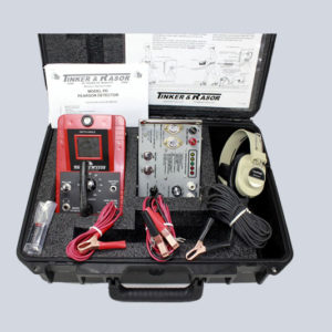
Mk V/S “Short Locator” comes with:
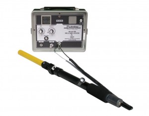
- Mark V “Ranger” Instrument
- Adapter, TS/8 to Ranger
- Headphones with adapter
- Connecting Cables
- Ground Plate
- Carrying Case
- (12) “C” Cell Batteries
- Instructions Manual
Mk-V/H Complete comes with everything the MK-V has plus:
- Cable Cleats (Set of 4)
- Cable Connecting Leads – 20′
- Shoe Cleats (2 pairs)
- Terminal Board Single Connect PD
- Terminal Board Double Connect PD
The Mark V “Ranger” can do it all: Finds shorts & opens, locate buried insulators, locate unknown pipes, locate unknown structures. Audio & Radio Frequencies, holiday inspections on buried pipes, accurate depth location, Inductive Operation, Conductive Operation, ECDA tool, Peak Method, Null Method.
Download a Brochure
 Downlad Mark V Ranger Brochure
The Newest addition to the Tinker & Rasor family of locators is the Mark V Ranger. This dual frequency locator affords the operator the luxury both Radio and Audio Frequencies. The Mark V Ranger delivers unrivaled performance at a very competitive price.
Although the Mark V has the potent combination of Power and Sensitivity this can be radically enhanced with the addition of the PD-5 Auxiliary Oscillator. This 25 watt powerhouse has been known to supply enough energy to a well coated pipeline to allow cross country surveys of 15 miles from a single connection point. The PD-5 Fits into the Mark V and allows the Mark V to close while the PD-5 is in place.
Download instructions
Download Mark V Ranger Instructions
1. Audio Frequency:
Pearson Type Holiday Detector:
The Tinker &Rasor Mark V Ranger set on audio frequency position was designed to locate discontinuities, flaws or breaks in the coating of buried pipelines. The method makes possible the exact location of coating breaks in buried lines without access to the surface of the coated pipe. Locating electrical discontinuities can be repaired to eliminate corrosion and to reduce the amount of current required for cathodic protection.
Short Locator:
The apparatus is also effective in locating shorts or undesirable electrical contacts to a contacts should be removed prior to placing a pipeline under cathodic protection as these contacts would drain a large amount of protective potential from the coated pipe.
Pipe Locator:
The apparatus can be used very effectively as a pipe locator on coated pipelines which are electrically connected by screw or welded joints. This applications is particularly effective where it is desired to locate and follow one pipeline along a right-of-way where there are a number of buried lines.
2. Operating Methods:
Pearson Survey Method:
The method used to locate discontinuities is that of applying audio frequency AC energy between the coated pipe and ground. A traverse along the pipeline is made in which the difference in potential is indicated across approximately twenty to thirty feet of soil above the line. This potential difference is noted in the receiver. When an area is reached where the difference in potential is considerably greater than the average potential over the pipe, a discontinuity is assumed to lie under this area.
Method of Locating Shorts:
The method of locating shorts or contacts on a coated pipe is that of applying AC audio frequency energy between the pipe and a remote ground connection. A traverse is made along the pipeline with a receiver equipped with a search coil. A short or contact is observed along the traverse where the average AC signal picked up over the line suddenly drops to a very low level. This is assumed to be a point directly above the contact.
Method of Locating Pipe:
An audio frequency AC signal is placed between the coated pipe and a good ground connection.The receiver, containing a search coil, is passed over the area where the pipe is assumed to be located. As the receiver is moved back and for thin a horizontal plane over the pipe, a sharp null will occur in the received signal. The pipe to be located is assumed to be directly under this null. A well coated pipeline can be followed for a great distance by this method.
3. Apparatus:
The complete apparatus furnished with the Mark V Ranger Detector includes the following:
- Receiver with battery*
- Transmitter with battery*
- Headphones, Stereo
- Shoe Cleats
- Connecting Cables
- Terminal Boards
- Carrying Case
Note: Li-Ion battery may be purchased as an optional accessory.
The Transmitter/Oscillator set on the audio frequency position has been designed to use the latest developments in this type of instrumentation. A digitally synthesized circuit,the Transmitter/Oscillator converts low voltage D.C. to stable audio frequency AC directly by a highly efficient method.
Transmitter/Oscillator:
In order that a maximum of energy can be transferred from the Transmitter/Oscillator to the pipe, the output of the Transmitter/Oscillator is provided with automatic impedance match to the load. An interrupter is provided to make the signal more easily recognized. Turning the Conductive/Inductive switch to the pulse position on the Transmitter/Oscillator actuates the interrupter.
Receiver:
The Receiver employs a high gain amplifier and sharply tuned 750-cycle filter. Modern circuit design insures maximum circuit stability even when operated at ambient temperature extremes. The filter attenuates AC power line and other interference’s,permitting operation in the vicinity of high-tension lines. A loudspeaker,with a volume control is built into the Receiver.
Plugging headphones into the jack marked PHONES disables the loudspeaker. Plugging the cables from the cleat terminal board into the jack marked INPUT automatically disconnects the search coil and connects the cleats to the amplifier. The meter gives a visual indication of the battery, turn the Gain Switch to test and turn the Receiver on. Replaced battery if necessary.
Shoe Cleats:
The shoe cleats provided with the detector have been designed for maximum foot comfort and for the most effective ground contact.
Connecting Cables:
All necessary connecting cables are furnished. Terminal Boards with belt loops are furnished and prove to be a convenient means of making the necessary connections between shoe cleats and the Receiver.
4. Unpack and Inspection:
Note the placement of the various components as received and repack in the same manner when not in use. If damage has occurred in shipment, file a claim with the carrier immediately. If it is necessary to contact your supplier or the manufacturer concerning damaged or missing items, be sure to include all the information such as serial numbers, purchase order number and invoice number. This will assure you of obtaining proper and expeditious service.
5. Operating Instructions:
A.Pearson Survey:
The following components are required for a Pearson Survey of a buried pipeline:
- Transmitter/Oscillator
- Receiver
- Connecting Cables &Terminals Board
- Two sets of Shoe Cleats
- Cleat Connecting Cables
- 25 Watt Oscillator (optional accessory, not required under normal conditions)
- 12- volt storage battery(not furnished, for use with optional oscillator)
The Transmitter/Oscillator set on the audio frequency position, is placed along the pipeline at a point where an electrical connection can be made to the pipe. Test point lead wires are convenient connections. Plug the Pipe and Ground Terminal Board into the jack marked OUTPUT . The pipe lead wire is connected to the terminal marked PIPE. Connect the ground wire to the terminal marked GROUND and then to some metal structure which is in good electrical contact with the earth. If no structure is available, a ground rod can be driven into the earth and an electrical connection made to it.
If the optional 25watt Oscillator is used, connect a 12 volt storage battery to the battery terminals, observing correct polarity. (RED is POSITIVE, BLACK is NEGATIVE).Turn the battery switch to “ON”. the output indicator should glow.
The terminal boards should be attached to the belts of the operators. The operator who carries the Receiver uses the board with the cord and plug. Both operators fasten cleats on their shoes, then attach cleat cables to each cleat, running the cable inside their pant legs. The key operator connects the wires from BOTH of his cleats to the LOWER terminal on his terminal board. The secondary operator connects the wires from both his cleats and one end of the long connecting cable to his terminal board. The other end of the connecting cable goes to the UPPER terminal of the key man’s terminal board. The plug coming from the key man’s terminal board is plugged into the jack marked OUTPUT on the Receiver. Set the Receiver to the audio frequency position and turn the unit “ON”. The apparatus is ready for use.
Walking over the pipe at a slow pace makes the traverse along the pipeline. Beginning adjacent to the Transmitter/Oscillator, set the Receiver sensitivity so that the signal from the Transmitter/Oscillator can be heard at a very lower level.As progress away from the
Transmitter/Oscillator is made, the signal may drop and the level can be raised again by increasing the sensitivity control. As the distance increases from the Transmitter/Oscillator,increase the Gain Switch to medium or high as required. A discontinuity is indicated by an INCREASE in average signal level, followed by a relatively sharp decrease, then another increase and then back to normal level as progress is made over the discontinuity.
The exact point of discontinuity lies under the point of decreased signal or null.. This,then, is the point halfway between the two operators. If a series of discontinuities exist in close proximity to each other, the null effect may not be heard,or very difficult to observe. In this case, one man walks along the line and the other walks at right angles to the line and discontinuity is noted by an INCREASE in signal directly over the fault.
B. locating Shorts or Contacts:
The following components are required for locating line shorts:
- Transmitter/Oscillator and Receiver
- Terminal Board, pipe and Ground
- Transmitter to Pipe Cable
- Ground Cable
The Transmitter/Oscillator and ground connections are made in the same manner as described in the PEARSON SURVEY above.
Turn on the Transmitter/Oscillator and the Receiver making sure that both are set on the audio frequency position. Advance the Receiver sensitivity control until the 750 cycle tone is heard in the loudspeaker and the signal intensity meter read slightly less than full scale. As the Receiver is moved back and forth across the pipe to which the Transmitter/Oscillator is connected, a very sharp decrease, or null, in the received signal will be observed when the Receiver is directly over the pipe. Using this null method, it is possible to trace the path of the pipeline as long as there is a relatively large amount of audio frequency flowing in it.
If the coated pipe is in contact with a foreign system, the audio current will leave the coated pipe at this pint and audio current will flow in the foreign systems. The same null effect will then be present on the foreign system as on the coated pipe from audio Transmitter/Oscillator to point of contact.
C. Locating Pipelines:
The apparatus and method required for locating welded or screwed pipe is the same as for locating shorts or contacts. After connecting the Transmitter/Oscillator,hold the Receiver level over the ground and note the intensity of the received signal. As the Receiver is brought near the pipe, the signal will gradually increase and then will null sharply as the Receiver passes directly over the pipe.
It is also possible to determine the depth of a pipe. First mark its exact center, using the method described above. Once the centering of the pipe has been accomplished,it is relatively easy to measure the depth by triangulation. in order to determine the depths of pipes, it is necessary to position the Receiver in a 45-degree angle to the ground surface. This is accomplished by holding the Receiver so that its longest axis is perpendicular to the path of the pipe and then tilting it back until the air bubble in the DEPTH ANGLE gauge lies between the outer edge of the center ring and black border.
Starting at the point directly above the pipe center line, and keeping the Receiver as close to the surface as possible without scratching it on the ground, move slowly away from the pipe at a right angle, maintaining the Receiver at a 45 degree.When a new null or minimum signal is obtained, the depth of the pipe below the surface is the same as the distance between the centerline of the pipe and the leading edge of the Receiver.
Refer to Detectron Model 505 “GO-FER” for Radio Frequency Instructions
6. Shipping Instructions:
All instruments being returned for repair should be sent PREPAID to either address below:
Ship Via Courier (UPS, FedEx, DHL, etc)
Tinker & Rasor
ATTN: Repairs
791 S. Waterman Ave.
San Bernardino, CA 92408
Include with shipment information the nature of the problem, purchase order, serial number
and return delivery address, phone and fax numbers. Immediate service is guaranteed!
Tech Data
Environment:
- 0ºC to 50ºC (32ºF to 122ºF)
Dimensions:
- Transmitter-11.375″ x 8.5″ weight 3.3 lbs. (289mm x 216mm x 76mm, 1.36kg)
- Receiver- 11.375″ x 8.5″ weight 3.4 lbs. (289mm x 216mm x 76mm, 1.81kg)
Mark V Short Parts List
Accessories Available
- #085-098 Mk V Ranger Instrument – US$1,100.00
- #010-025 “C” Cell Battery – US$2.33 Each MV5 Takes 12 Each
- #026-062 Cable, Audio Frequency Ranger – US$30.00
- #115-013 Headphones Stereo – US$28.75
- #009-021 Adapter, Headphones – US$3.77
- #116-028 Ground Plate – US$6.00
- #010-038 Li-Ion Rechargeable Battery order with 031-023-VEN Charger – US$146.50
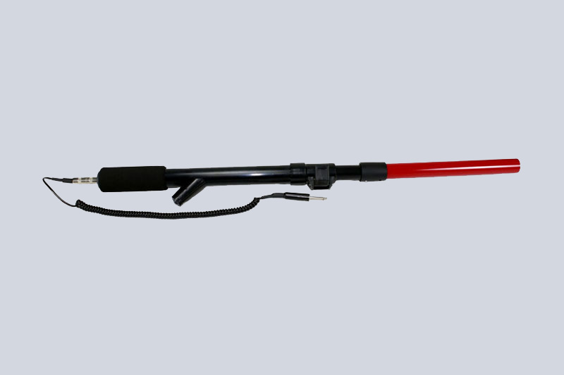
- #085-087 Detectron TS/8 Handheld Probe – US$195.00
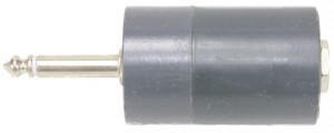
- #009-014 Adapter, TS/8 to MkV Ranger – US$10.00

Detectron Model: TS/8 Handheld Probe (Shown here with Detectron 505 “GOFER”)
#009-014 Adapter TS/8 to Mk5 “Ranger”
Mark V Complete Parts List
Accessories Available
- #085-098 Mark V Instrument – US$1,200.00
- #010-025 “C” Cell Battery – US$2.33 Each Mk-V Takes 12 each
- #026-008 20′ Cable Connecting Lead – US$12.65
- #026-006 Cable Cleats Set of 4 – US$33.00
- #026-062 Cable, Audio Frequency Ranger – US$30.00
- #035-002 Cleats (2 pair) – US$101.20
- #115-013 Headphones, Stereo – US$28.75
- #009-021 Adapter, Headphones – US$3.77
- #116-028 Ground Plate – US$6.00
- #164-012 Terminal Board Single Connect – US$15.18
- #164-024 Terminal Board Double Connect – US$31.65
- #010-038 Li-Ion Rechargeable Battery order with 031-023-VEN Charger – US$146.50
- #009-014 Adapter TS/8 to MkV Ranger – US$10.00
- #TS-8 (Detectron) US$195.00

#010-025 “C” Cell Battery MK-V Uses 12


Reviews
There are no reviews yet.